EZVIZ BD-2402B1 Back Engineering and SNES9X Port
Table Of Contents
- Introduction
- Hardware Details
- SoC - Hi3520DV300
- JTAG - Hardware Debugging
- Hisilicon Source Code
- Bricking The Device & Bus Pirate
- Flashing SPI NOR Flash Chip (MX25L12835F)
- Custom UBoot & Custom Kernel
- System Startup
- Configuring Pinmux’s & Loading Kernel Modules
- SNES9X Port
- Conclusion
Introduction
EZVIZ BD-2402B1 is a surveillance system DVR which uses hisilicon SoC’s. My goal was to repurpose the hardware to run a custom fork of snes9x. In order to achieve this a serious amount of reverse engineering, and learning was required. Not only was this a hardware based project, but it was also a software heavy project.
I decided I would try and run my own snes9x fork on this hardware rather than do security related research after reviewing many articles detailing serious security vulnerabilities in products using hisilicon SoC’s. I felt that there were already enough eyes on the software running on these boards that another set of eyes would not add anything of value. In addition, hisilicon has been banned from the USA recently and so the amount of people using these camera systems is in decline. The chances of me finding a new vulnerability combined with the declining impact (usage) alluded to repurposing the hardware.
So, instead, I decided I would take the opportunity to expand my hardware hacking skill set and familiarise myself with an snes emulator ive used for many years (snes9x).
Hardware Details
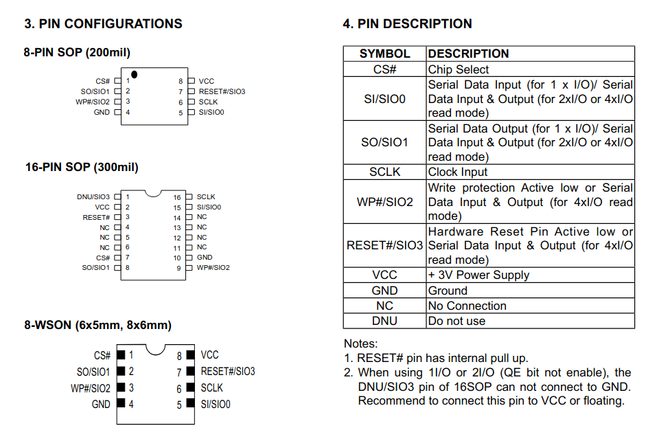
To begin, the components/peripherals on the board should be described. Only the components which are of interest to porting snes9x and obtaining code execution on the device will be described, the rest of the components are well documented in the processor data sheet PDF hosted here.
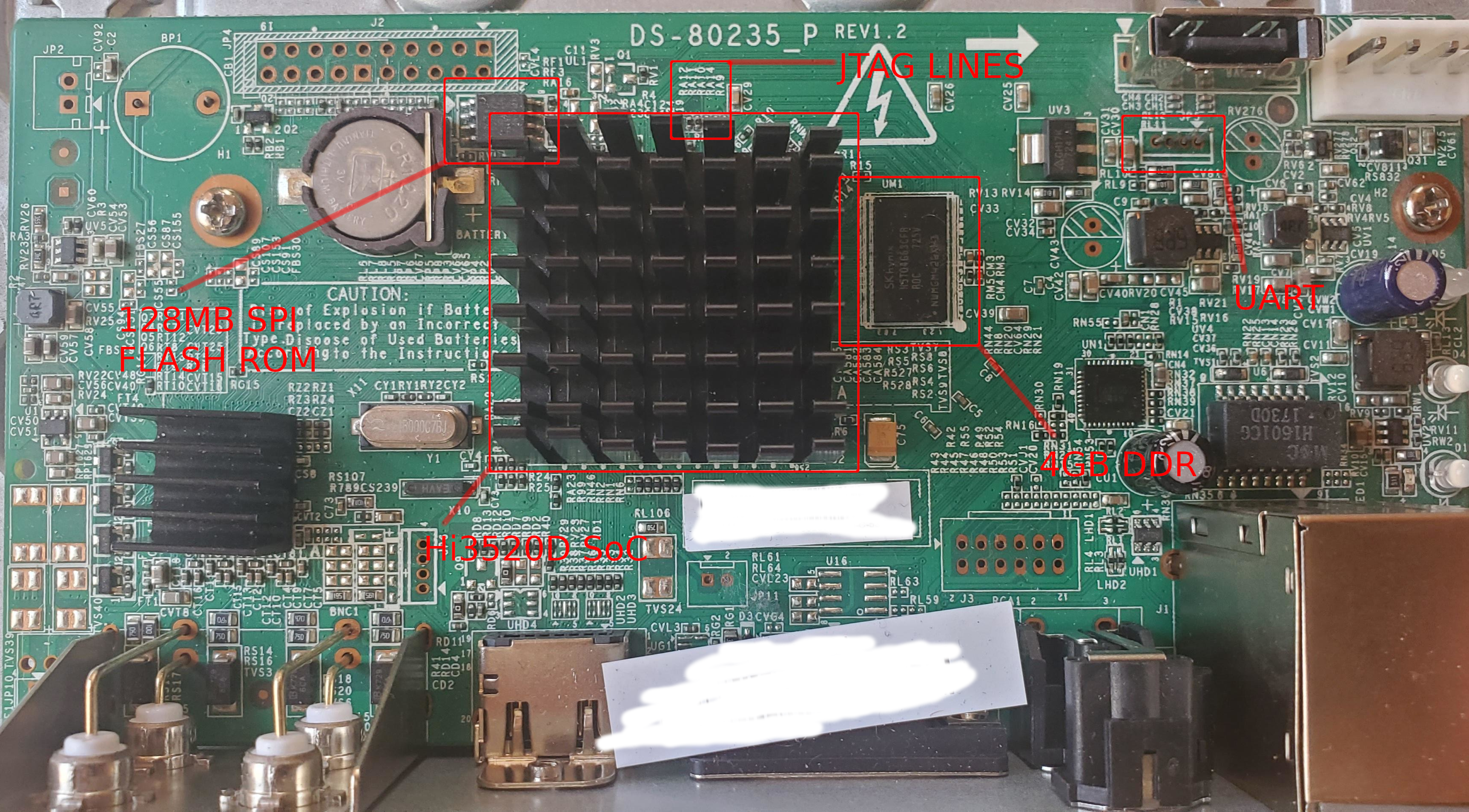
The pin headers which are on the board are NC (no connect) as their resistors have been removed from the PCB. Some pins are not NC, such as ground, since they are directly connected to a ground plain.
Notable Components
- 128MB SPI Flash Rom - MX25L12835F
- 4GB DDR Ram - H5TQ4G63CFR
- SoC - Hi3520D V300
A full, detailed list of the other I/O can be found in the Brief data sheet (which is publicly available). You can find a re-hosted version of that PDF here.
SoC - Hi3520DV300
“Hi3520D V300 is a professional SoC targeted for the multi-channel HD (1080p/720p) or SD (D1/960H) DVR. Hi3520D V300 provides an ARM A7 processor, a high-performance H.264 video encoding/decoding engine, a high-performance video/graphics processing engine with various complicated graphics processing algorithms, HDMI/VGA HD outputs, and various peripheral interfaces. These features enable Hi3520D V300 to provide high-performance, high-picture-quality, and low-cost analog HD/SDI solutions for customers' products while reducing the eBOM cost”
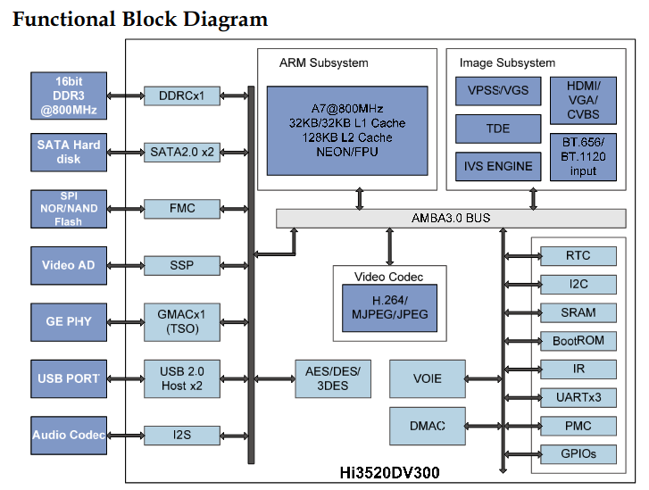
TDE - Two Dimensional Engine
The TDE is a graphics processing engine which runs outside of the arm processor. This allows for offloading of complex bitmap operations to happen without using the main processor. This engine is documented in the TDE programmers user manual. This engine helps in accelerating operations such as copying a bitmap into another and respecting the pitch (number of bytes per horizontal lines of pixels). It also can do pixel format conversions (which as you will see later in the post are required). Bitmap scaling is also done in this engine.
UART - Universal asynchronous receiver-transmitter
The uboot on the board when I received it configured the UART baud rate to be 115200 baud. The TX pin was intact/connected. I was able to interrupt uboot easily, which allowed me to set rdinit=/bin/sh for the kernel cmdline (bootargs).
I was setting init=/bin/sh and seeing no effect for a while because I didn’t realise the kernel was using an initramfs/initrd configuration. The entire file system is contained inside of the kernel image and is uncompressed and represented in memory. This also implies no persistent changes to the root filesystem were possible without recompiling the entire linux kernel and flashing it.
setenv bootargs mem=128M console=ttyAMA0,115200n8 rdinit=/bin/sh
This presented me with a root shell after booting the kernel as opposed to the PSH shell. The PSH shell is a restricted shell which doesn’t allow you to interact with the operating system normally. It’s more about checking statuses and such.
Having root access to the device gave me useful information such as the SoC product number. This information allowed me to locate leaked source code pertaining to this SoC.
JTAG - Hardware Debugging
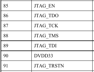
The SoC does have JTAG however all pin headers are not connected as resistors have been removed by the manufacturer. The SoC uses pins 85-91 for JTAG related functionality. This is something of further interest, however it’s not directly useful for this project as I already have full control over everything.
Hisilicon Source Code
Which can be found here, rehosted on my servers…
Note:
If Hisilicon reaches out to me and requests I remove such content I shall. If the link is dead then you can assume the former has happened.
Some parts of the SDK are already on github.
These repos contain almost everything:
This project would not have been possible if it were not for a Chinese friend of mine who was able to download the entire leaked SDK off of https://www.csdn.net. This website requires a Chinese phone number (non-VOIP) to register an account, and you also need an account to download source code. His contribution to the project is invaluable. For his sake (and by his request) he will remain unnamed.
The leaked source code contains uboot, linux kernel 3.10, extremely detailed documentation for the SoC, schematics, MPP source code (which is publicly available), and much more. This SDK is mentioned in the Brief Data Sheet. Without this source code nor documentation of the gpio/pinmux memory layout, communication over UART, as well as many other peripherals (including HDMI output) could not be configured.
Bricking The Device & Bus Pirate
The SDK comes with precompiled binaries for two platforms. I wanted to ensure that I found the correct SDK pertaining to my hardware so I decided I would overwrite uboot with one of the precompiled uboot images found in the SDK. I used some of the commands provided by uboot to do this.
These commands are used as so:
- Read the pre-compiled uboot image over ethernet using tftp into memory at 0x82000000
- Probe the first SPI device and set it as the default (initialise functionality such as sf read and sf write)
- Write the uboot image from memory to the flash memory at offset 0. The arm processor will begin execution at address 0 (reset vector). Finally reset the processor.
tftp uboot-from-sdk.bin 0x82000000
sf probe 0
sf write 0x82000000 0 0x100000
reset
After executing these uboot commands I received nothing out of UART and so I concluded I had flashed the wrong uboot image. There were actually two pre-compiled uboot images in the SDK. I then started working with the SPI NOR flash memory directly using my bus pirate.
However the firmware on my bus pirate has known issues with flashrom…
During the firmware upgrade and bootloader upgrade process of the bus pirate I unplugged it as I do this to close the screen I open to view the Bus Pirate.
# if you unplug the bus pirate the screen program terminates
screen /dev/ttyUSB0 115200
So, my bad habit of unplugging the device to close the screen ended up costing me 35$ and a few days of time on the project.
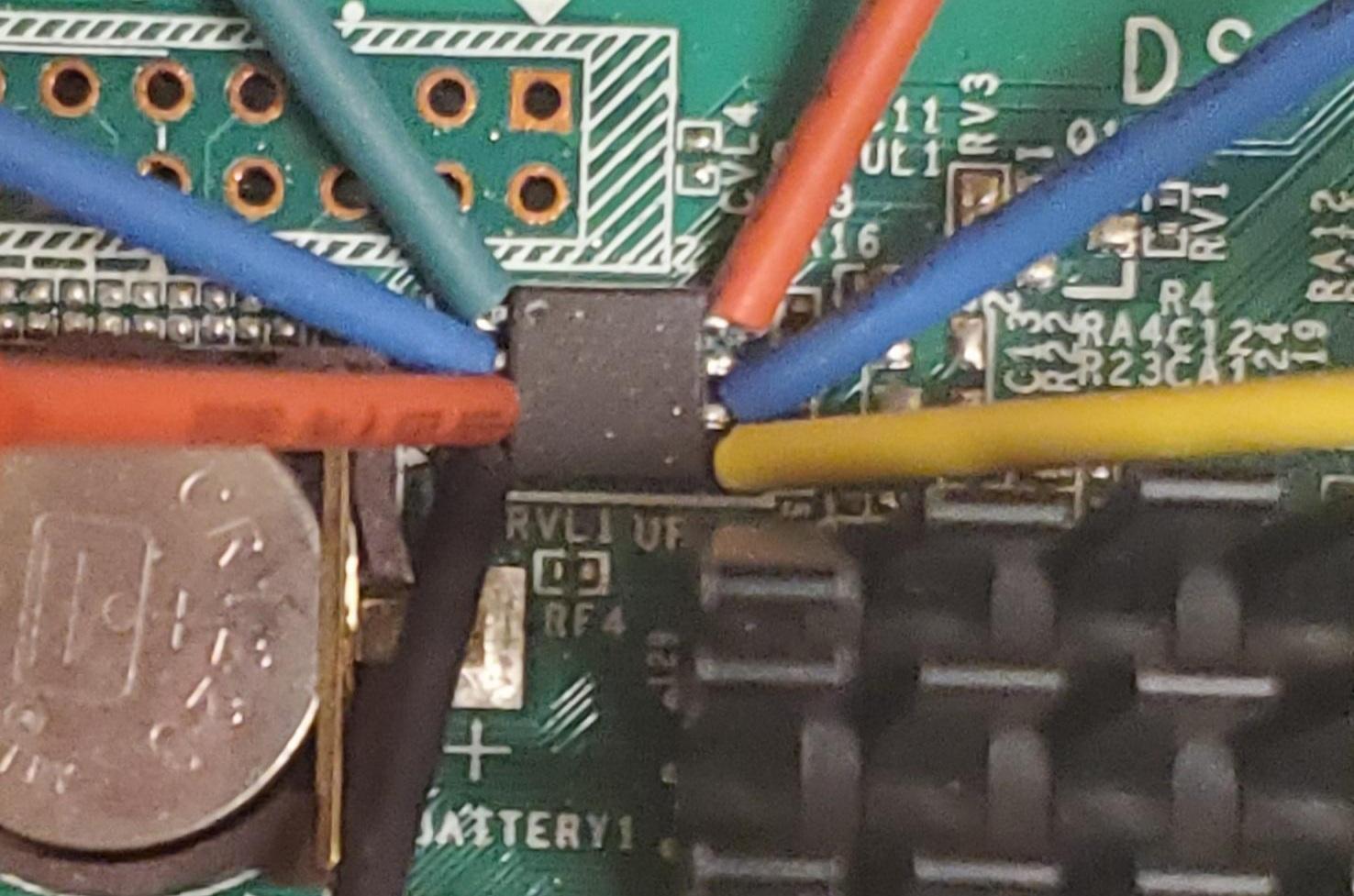
Flashing SPI NOR Flash Chip (MX25L12835F)
Connections must be made to VCC, CS#, SO, SI, and GND between the bus pirate and flash chip. The WP# pin must be held high in order for write protection to be disabled. This will allow flashrom to send commands to change the status register of the flash which can then allow flashrom to disable write protection on all blocks of memory.
After configuration it should look something like this:
Finally flashing the second of the precompiled uboot images onto the nor flash chip I was able to see UART output. This confirmed my original suspicion which was that I unintentionally flashed the wrong precompiled uboot image onto the chip.
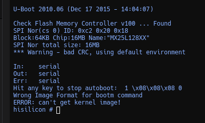
Now that I know I can flash uboot images to the NOR flash it’s time to start developing a custom uboot and kernel image.
Custom UBoot & Custom Kernel
In order for me to load a custom kernel image I require more control over the boot sequence. Therefore I found it necessary to edit a few variables in the uboot configuration. Firstly, I will not be storing a CRAMFS filesystem on the flash chip, rather I will store the kernel at a predefined location in the flash memory. The only reason for recompiling the kernel is because the file system in which linux uses will be stored inside of the linux kernel. Init.d scripts are thus compiled into the kernel and so any changes to the file system require recompiling the entire kernel.
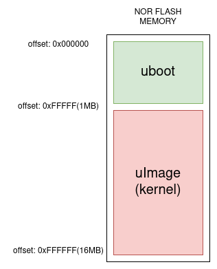
Uboot is only ~200KB so for rounding sake it will be truncated to 1MB. The resulting custom kernel image will then be truncated to 15MB. Both uboot and the linux kernel will be concatenated together as one large 16MB file. Finally the resulting file (u-boot-done.bin) is flashed.
truncate –size=1M u-boot.bin
truncate –size=15M uImage
cat u-boot.bin uImage > u-boot-done.bin
flashrom -V -p buspirate_spi:dev=/dev/ttyUSB0,spispeed=2M \
	-c MX25L12835F/MX25L12845E/MX25L12865E -w u-boot-done.bin
The custom boot command for uboot is the following:
sf probe 0 # sf initialization
sf read 0x82000000 0x100000 0x700000 # reads 7mb from offset=1MB into address 0x82000000
bootm 0x82000000 # boot the custom kernel
This allows me to remove the need for a CRAMFS file system or any file system stored on the flash memory itself.
System Startup
The SDK contains a preconfigured busybox which is essentially all executables required to operate the system stored in a single executable. Busybox will operate as the init program, which is the first usermode executable to run (PID 1). Init will parse and execute commands from the /etc/inittab file.
/etc/inittab executes the bash script /etc/init.d/rcS. /etc/init.d/rcS will execute mount -a and then execute the rest of the bash scripts in the same folder. These other bash scripts must be of the naming convention: SXX where XX is a number, the number represents precedence in execution.
System Startup Overview
- Uboot
- uImage loaded
- Kernel decompressed
- Control passed to the kernel
- Kernel startup
- Execution passed to
/init /initparses and executes commands from/etc/inittab/etc/inittabsays to execute/etc/init.d/rcS/etc/init.d/rcSexecutesmount -aand then executes other bash scripts.mount -awill mount file systems according to /etc/fstab.echo /sbin/mdev > /proc/sys/kernel/hotplugmdev -s- pinmux’s are configured and hisilicon kernel modules are loaded
- Lastly a getty executable is launched and the root user is logged in without authentication.
- Root user
/root/.profileconfigures environment variables and lastly executes the snes9x fork.
The first USB plugged into the device will be /dev/sda with the first recognizable partition /dev/sda1. The startup scripts will mount the USB via mount /dev/sda1 /mnt/usb-drive/. The last command executed by my startup scripts executes a script by the file name “snes9x” on the USB. This will allow me to run stuff at init.d without recompiling and reflashing the kernel image to the flash.
Configuring Pinmux’s & Loading Kernel Modules
When the system is brought up, certain pins are configured in a manner which will render kernel module functionality inoperable. Such is the case with HDMI output. The SDK contains configuration shell scripts that set pinmux configurations so that when kernel modules are loaded their functionality is successful. These are important so I will list them all here:
# pinmux configuration
#I2C
himm 0x120F00E0 0x1; # 0:GPIO12_6  1:I2C_SDA
himm 0x120F00E4 0x1; # 0:GPIO12_7  1:I2C_SCL

#VICAP
himm 0x120F0000 0x2;  # 00:GPIO5_7  01:VI0_CLK   10:VI_ADC_REFCLK0

himm 0x120F0004 0x1;  #  0:GPIO1_0   1:VI0_DAT7
himm 0x120F0008 0x1;  #  0:GPIO1_1   1:VI0_DAT6
himm 0x120F000C 0x1;  #  0:GPIO1_2   1:VI0_DAT5
himm 0x120F0010 0x1;  #  0:GPIO1_3   1:VI0_DAT4
himm 0x120F0014 0x1;  #  0:GPIO1_4   1:VI0_DAT3
himm 0x120F0018 0x1;  #  0:GPIO1_5   1:VI0_DAT2
himm 0x120F001C 0x1;  #  0:GPIO1_6   1:VI0_DAT1
himm 0x120F0020 0x1;  #  0:GPIO1_7   1:VI0_DAT0

himm 0x120F0024 0x2;  # 00:GPIO10_6 01:VI1_CLK   10:VI0_CLK

himm 0x120F0028 0x1   #  0:GPIO2_0   1:VI1_DAT7
himm 0x120F002C 0x1   #  0:GPIO2_1   1:VI1_DAT6
himm 0x120F0030 0x1   #  0:GPIO2_2   1:VI1_DAT5
himm 0x120F0034 0x1   #  0:GPIO2_3   1:VI1_DAT4
himm 0x120F0038 0x1   #  0:GPIO2_4   1:VI1_DAT3
himm 0x120F003C 0x1   #  0:GPIO2_5   1:VI1_DAT2
himm 0x120F0040 0x1   #  0:GPIO2_6   1:VI1_DAT1
himm 0x120F0044 0x1   #  0:GPIO2_7   1:VI1_DAT0

himm 0x120F0048 0x2;  # 00:GPIO6_0   01:VI_ADC_REFCLK0   10:VI1_CLK
himm 0x120F004C 0x2;  # 00:GPIO11_7  01:VI2_CLK          10:VI_ADC_REFCLK1

himm 0x120F0050 0x1   #  0:GPIO3_0   1:VI2_DAT7
himm 0x120F0054 0x1   #  0:GPIO3_1   1:VI2_DAT6
himm 0x120F0058 0x1   #  0:GPIO3_2   1:VI2_DAT5
himm 0x120F005C 0x1   #  0:GPIO3_3   1:VI2_DAT4
himm 0x120F0060 0x1   #  0:GPIO3_4   1:VI2_DAT3
himm 0x120F0064 0x1   #  0:GPIO3_5   1:VI2_DAT2
himm 0x120F0068 0x1   #  0:GPIO3_6   1:VI2_DAT1
himm 0x120F006C 0x1   #  0:GPIO3_7   1:VI2_DAT0

himm 0x120F0070 0x2;  # 00:GPIO10_5   01:VI3_CLK   10:VI2_CLK

himm 0x120F0074 0x1   #  0:GPIO4_0   1:VI3_DAT7
himm 0x120F0078 0x1   #  0:GPIO4_1   1:VI3_DAT6
himm 0x120F007C 0x1   #  0:GPIO4_2   1:VI3_DAT5
himm 0x120F0080 0x1   #  0:GPIO4_3   1:VI3_DAT4
himm 0x120F0084 0x1   #  0:GPIO4_4   1:VI3_DAT3
himm 0x120F0088 0x1   #  0:GPIO4_5   1:VI3_DAT2
himm 0x120F008C 0x1   #  0:GPIO4_6   1:VI3_DAT1
himm 0x120F0090 0x1   #  0:GPIO4_7   1:VI3_DAT0

himm 0x120F0094 0x2;  # 00:GPIO6_1  01:VI_ADC_REFCLK1     10:VI3_CLK

#VGA
himm 0x120F0098 0x1;   # 0: GPIO11_6  1: VGA_HS
himm 0x120F009C 0x1;   # 0: GPIO11_3  1: VGA_VS

#HDMI
himm 0x120F0174 0x1;   # 0: GPIO13_4  1:HDMI_HOTPLUG
himm 0x120F0178 0x1;   # 0: GPIO13_5  1:HDMI_CEC
himm 0x120F017C 0x1;   # 0: GPIO13_6  1:HDMI_SDA
himm 0x120F0180 0x1;   # 0: GPIO13_7  1:HDMI_SCL

#SPI
himm 0x120F00C4 0x1;   # 00:TEST_CLK 01:SPI_SCLK 10:GPIO5_0
himm 0x120F00C8 0x1;   # 0: GPIO5_1   1:SPI_SDO
himm 0x120F00CC 0x1;   # 0: GPIO5_2   1:SPI_SDI
himm 0x120F00D0 0x1;   # 0: GPIO5_3   1:SPI_CSN0
himm 0x120F00D4 0x1;   # 0: GPIO5_4   1:SPI_CSN1

#I2C
himm 0x120F00E0 0x1; # 0:GPIO12_6  1:I2C_SDA
himm 0x120F00E4 0x1; # 0:GPIO12_7  1:I2C_SCL

#I2S
himm 0x120F00A0 0x1; # 0: GPIO9_0   1: I2S0_BCLK_RX
himm 0x120F00A4 0x1; # 0: GPIO9_1   1: I2S0_WS_RX
himm 0x120F00A8 0x1; # 0: GPIO9_2   1: I2S0_SD_RX

himm 0x120F00AC 0x2; # 00: GPIO9_3  01: I2S1_BCLK_RX  10:I2S2_MCLK
himm 0x120F00B0 0x1; # 0: GPIO9_4   1: I2S1_WS_RX
himm 0x120F00B4 0x1; # 0: GPIO9_5   1: I2S1_SD_RX

himm 0x120F00B8 0x1; # 0: GPIO9_6   1: I2S2_BCLK_TX
himm 0x120F00BC 0x1; # 0: GPIO9_7   1: I2S2_WS_TX
himm 0x120F00C0 0x1; # 0: GPIO5_4   1: I2S2_SD_TX

# crg configuration
#VI(0x5c001111--150M,0x3c001111--324M,0x1c001111--300M)
himm 0x1204002c 0x1c001111 #720p

#VI ADC REF0/REF1
himm 0x120400B4 0x00000035

#TDE
himm 0x12040048 0x00000002

#IVE
himm 0x1204005C 0x00000002

#CIPHER
himm 0x12040060 0x00000002

# system configuration
######### MISC QOS setting! ######

himm 0x1212007c 0x44443201  ## VGS-JPGD-IVE -TDE -AVC0- A7 - VO -VI
himm 0x12120080 0x26334444  ## GSF-DDRT-AVC1-VPSS-VOIE-JPGE-AIO-MDU
himm 0x12120084 0x66666426  ## ###-DMAm0-DMAm1-FMC-USB2-CIPHER-SCD-SATA

#######VIVO 总线优先级 7优先级最大###########
himm 0x12120094 0x65   ###【2:0】VI   【6:4】VO

###############################
## mddrc0 pri&timeout setting #
###############################
himm  0x12110020  0x00000001  # AXI_ACTION[19:8]:wr_rcv_mode=0,12ports

himm  0x12110200  0x00370000  # ports0 选择随路QOS模式
himm  0x12110210  0x00370000  # ports1
himm  0x1211021c  0x08300830  # ports1读写自适应优先级
himm  0x12110220  0x00370000  # ports2
himm  0x1211022c  0x08300830  # port2读写自适应优先级
himm  0x12110230  0x00370000  # ports3
himm  0x1211023c  0x08300830  # port3读写自适应优先级
himm  0x12110240  0x00370000  # ports4
himm  0x12110250  0x00370000  # ports5
himm  0x12110260  0x00370000  # ports6
himm  0x12110270  0x00370000  # ports7
##DDRC AXI pri ports0 - 7
############## WR pri ##############
himm  0x12110204  0x76543210  # ports0
himm  0x12110214  0x76543210  # ports1
himm  0x12110224  0x76543210  # ports2
himm  0x12110234  0x76543210  # ports3
himm  0x12110244  0x76543210  # ports4
himm  0x12110254  0x76543210  # ports5
himm  0x12110264  0x76543210  # ports6
himm  0x12110274  0x76543210  # ports7
############## RD pri ##############
himm  0x12110208  0x76543210  # ports0
himm  0x12110218  0x76543210  # ports1
himm  0x12110228  0x76543210  # ports2
himm  0x12110238  0x76543210  # ports3
himm  0x12110248  0x76543210  # ports4
himm  0x12110258  0x76543210  # ports5
himm  0x12110268  0x76543210  # ports6
himm  0x12110278  0x76543210  # ports7
##############  qosbuf #############
himm  0x12114000  0x00000002   #qosb_push_ctrl
himm  0x12114004  0x000007F1   #cycle
himm  0x1211410c  0x0000000a   #qosb_dmc_lvl
himm  0x12114110  0x0000000a   #qosb_dmc_lvl
himm  0x1211408c  0xb3032010   #qosb_wbuf_ctrl
himm  0x12114090  0xb3032010   #qosb_wbuf_ctrl
himm  0x121140f4  0x00000033   #row-hit enable
himm  0x121140ec  0x00000044   #row-hit
himm  0x121140f0  0x00003333   #row-hit
himm  0x121141f4  0x00000000   #qosb_wbuf_pri_ctrl

himm  0x121141f0  0x00000001   #enable qosbuf timeout,through prilvl to remap timeout level
############## WR timeout ###########
himm  0x1211409c  0x00000010  # wr_tout3 ~wr_tout0
himm  0x121140a0  0x00000000  # wr_tout7 ~wr_tout4
himm  0x121140a4  0x00000000  # wr_tout11~wr_tout8
himm  0x121140a8  0x00000000  # wr_tout15~wr_tout12

############## RD timeout ###########
himm  0x121140ac  0x00000010  # rd_tout3 ~rd_tout0
himm  0x121140b0  0x00000000  # rd_tout7 ~rd_tout4
himm  0x121140b4  0x00000000  # rd_tout11~rd_tout8
himm  0x121140b8  0x00000000  # rd_tout15~rd_tout12

himm  0x121141f8  0x00800002  # qosb_rhit_ctrl,open_window=128,close_window=2
Each of these addresses functionality is well defined in the SoC PDF. The executable himm is simply a mmap wrapper that allows command line editing of physical memory. The source code for this tool is contained inside of the SDK.
SNES9X Port
The last part of this project was actually writing the snes9x port. To begin, a good read over porting.html is required. The document states that there are some methods that must be implemented however most can simply be null subroutines.
To make things easier there is existing unix code for the snes9x unix port. However this unix code contains x11 code which is not applicable to my port.
The following routines were simply copied from the unix.cpp file:
bool8 S9xMapInput(const char *n, s9xcommand_t *cmd);
void InitJoysticks(void);
bool8 ReadJoysticks(void);
const char *S9xStringInput(const char *message);
const char *S9xGetFilename(const char *ex, s9x_getdirtype dirtype);
const char *S9xGetFilenameInc(const char *ex, enum s9x_getdirtype dirtype);
const char *S9xGetDirectory(enum s9x_getdirtype dirtype);
const char *S9xBasename(const char *path);
The only function of true interest is S9xDeinitUpdate which is called everytime a frame is computed and ready to be rendered. All of the scaling and pixel conversion logic must be performed inside of this function.
SNES9X Rendering
Porting x11/xorg to run on this embedded device is a no go due to size constraints. There will be no graphics libraries on the system as well (no SDL, OpenGL, etc). My snes9x fork will simply render directly to the frame buffer device /dev/fb0. The hisilicon documentation for the framebuffer is detailed and the SDK even contains examples of how to operate the frame buffer device. HiFB API Reference.pdf, HiFB Development Guide
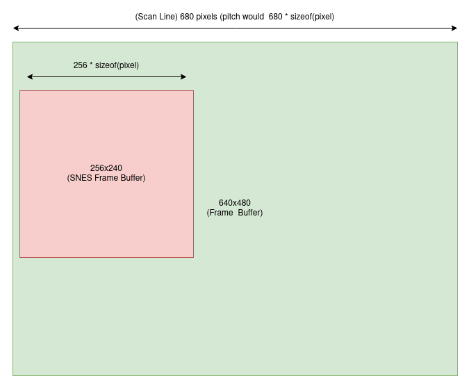
The hisilicon SDK contains example code on how to display images to the frame buffer. The steps are: initialise the display device, then setup a display layer. The game I want to emulate (Super Mario World) has a pixel resolution of 256x240. My idea was to init the video output device to display at the lowest possible resolution so that upscaling the SNES output would require less work. The lowest the hisilicon HDMI output supports is 680x480 at 60HZ. This means upscaling will only be a little over x2.
The following code is used to setup HDMI at 640x480 resolution:
/******************************************
 step  1: init variable
******************************************/
memset(&stVbConf, 0, sizeof(VB_CONF_S));

u32BlkSize = CEILING_2_POWER(u32PicWidth, SAMPLE_SYS_ALIGN_WIDTH) *
             CEILING_2_POWER(u32PicHeight, SAMPLE_SYS_ALIGN_WIDTH) * 2;

stVbConf.u32MaxPoolCnt = 128;
stVbConf.astCommPool[0].u32BlkSize = u32BlkSize;
stVbConf.astCommPool[0].u32BlkCnt = 6;

/******************************************
 step 2: mpp system init.
******************************************/
s32Ret = SAMPLE_COMM_SYS_Init(&stVbConf);
if (HI_SUCCESS != s32Ret) {
  SAMPLE_PRT("system init failed with %d!\n", s32Ret);
  return HI_FALSE;
}

/******************************************
 step 3:  start vo hd0.
*****************************************/
s32Ret = HI_MPI_VO_UnBindGraphicLayer(GRAPHICS_LAYER_HC0, SAMPLE_VO_DEV_DHD0);
if (HI_SUCCESS != s32Ret) {
  SAMPLE_PRT("UnBindGraphicLayer failed with %d!\n", s32Ret);
  return HI_FALSE;
}

s32Ret = HI_MPI_VO_BindGraphicLayer(GRAPHICS_LAYER_HC0, SAMPLE_VO_DEV_DHD0);
if (HI_SUCCESS != s32Ret) {
  SAMPLE_PRT("BindGraphicLayer failed with %d!\n", s32Ret);
  return HI_FALSE;
}

stPubAttr.enIntfSync = VO_OUTPUT_640x480_60;
stPubAttr.enIntfType = VO_INTF_HDMI;
stPubAttr.stSyncInfo.bSynm = HI_TRUE;
stPubAttr.u32BgColor = 0x000000;  // background will be black

stLayerAttr.bClusterMode = HI_FALSE;
stLayerAttr.bDoubleFrame = HI_FALSE;
stLayerAttr.enPixFormat = PIXEL_FORMAT_YUV_SEMIPLANAR_420;

u32VoFrmRate = 60;
stSize.u32Width = SCREEN_WIDTH;
stSize.u32Height = SCREEN_HEIGHT;

memcpy(&stLayerAttr.stImageSize, &stSize, sizeof(stSize));

stLayerAttr.u32DispFrmRt = 60;
stLayerAttr.stDispRect.s32X = 0;
stLayerAttr.stDispRect.s32Y = 0;
stLayerAttr.stDispRect.u32Width = stSize.u32Width;
stLayerAttr.stDispRect.u32Height = stSize.u32Height;

s32Ret = SAMPLE_COMM_VO_StartDev(SAMPLE_VO_DEV_DHD0, &stPubAttr);
if (HI_SUCCESS != s32Ret) {
  SAMPLE_PRT("start vo dev failed with %d!\n", s32Ret);
  return HI_FALSE;
}

s32Ret = SAMPLE_COMM_VO_StartLayer(VoLayer, &stLayerAttr);
if (HI_SUCCESS != s32Ret) {
  SAMPLE_PRT("start vo layer failed with %d!\n", s32Ret);
  return HI_FALSE;
}

if (stPubAttr.enIntfType & VO_INTF_HDMI) {
  s32Ret = SAMPLE_COMM_VO_HdmiStart(stPubAttr.enIntfSync);
  if (HI_SUCCESS != s32Ret) {
    SAMPLE_PRT("start HDMI failed with %d!\n", s32Ret);
    return HI_FALSE;
  }
}
Relevant Graphics Concepts
Before jumping into things it’s best to explain some basics. In graphics rendering there is a term “pitch” which simply means “the number of bytes for a single vertical line of pixels”. This is important because overlapping bitmap images requires skipping X amount of bytes before writing the next vertical line of pixels (assuming both bitmaps are of different size). Hisilicon TDE handles overlapping and deals with pitch for us so we don’t need to!
Pixel formatting is also important to understand. The SNES9X emulator uses RGB565 by default, the hisilicon framebuffer device uses ARGB1555 by default and thus a pixel conversion is required. The TDE engine also handles pixel conversion to a certain extent.
Hardware Accelerated SNES9X with the TDE
Now that those basic graphics concepts are out of the way we can look into the TDE. The TDE as explained earlier in the post is a two dimensional graphics engine which can be used to offload scaling, overlapping, and pixel conversion operations so that the main ARM processor does not need to do that. The following API functions are of interest. These functions are inside of libtde.a and the code inside of libtde.a is essentially a wrapper function around ioctl. The TDE driver must be loaded into the linux kernel, this TDE driver depends upon the MMZ (media memory zone) driver.
HI_S32 HI_TDE2_Open(HI_VOID);

TDE_HANDLE HI_TDE2_BeginJob(HI_VOID);

HI_S32 HI_TDE2_QuickCopy(TDE_HANDLE s32Handle,
	TDE2_SURFACE_S *pstSrc,
	TDE2_RECT_S *pstSrcRect,
	TDE2_SURFACE_S *pstDst,
	TDE2_RECT_S *pstDstRect);

HI_S32 HI_TDE2_Bitblit(TDE_HANDLE s32Handle,
	TDE2_SURFACE_S *pstBackGround,
	TDE2_RECT_S *pstBackGroundRect,
	TDE2_SURFACE_S *pstForeGround,
	TDE2_RECT_S *pstForeGroundRect,
	TDE2_SURFACE_S *pstDst,
	TDE2_RECT_S *pstDstRect,
	TDE2_OPT_S *pstOpt);

HI_S32 HI_TDE2_EndJob(TDE_HANDLE s32Handle,
	HI_BOOL bSync, HI_BOOL bBlock,
	HI_U32 u32TimeOut);

HI_S32 HI_TDE2_WaitAllDone(HI_VOID);
A full documentation of these functions is provided in the TDE API Reference Manual.
The most notable of these functions is the HI_TDE2_Bitblit function which allows for all sorts of operations to take place. The most important operations for the snes9x port is pixel conversion, and scaling. Both of these operations can be done at the exact same time using HI_TDE2_Bitblit.
stSrcRect.s32Xpos = 0;
stSrcRect.s32Ypos = 0;
stSrcRect.u32Height = SNES_HEIGHT;
stSrcRect.u32Width = SNES_WIDTH;

stSrc.enColorFmt = TDE2_COLOR_FMT_RGB565;
stSrc.u32Width = SNES_WIDTH;
stSrc.u32Height = SNES_HEIGHT;
stSrc.u32Stride = 2 * SNES_WIDTH;
stSrc.u32PhyAddr = g_pSnesBackBufferPhys;

stScaleRect.s32Xpos = 0;
stScaleRect.s32Ypos = 0;
stScaleRect.u32Height = SCALE_HEIGHT;
stScaleRect.u32Width = SCALE_WIDTH;

stScale.enColorFmt = TDE2_COLOR_FMT_ARGB1555;
stScale.u32Width = SCALE_WIDTH;
stScale.u32Height = SCALE_HEIGHT;
stScale.u32Stride = SCALE_WIDTH * 2;
stScale.u32PhyAddr = g_pScaleBufferPhys;

s32Ret = HI_TDE2_Bitblit(s32Handle, &stScale, &stScaleRect, &stSrc, &stSrcRect,
                         &stScale, &stScaleRect, &stOpt);
When the SNES draws black pixels it sets R, G, and B values to 0. This results in the pixel’s entire value being 0. The TDE engine is unable to convert RGB565 to ARGB1555 if the pixel value is 0. I am unsure why, but to fix this issue, I simply do a little error handling:
// if the screen is black all pixel values will be 0. this will cause bitblit
// to fail because it doesn't understand pixel conversions with pixels that are
// all 0... so i just make R = 1, G = 1, and B = 1... simple fix... lol...
if (s32Ret < 0) {
  for (int i = 0; i < SNES_WIDTH * SNES_HEIGHT; ++i) {
    if (*(((uint16_t*)g_pSnesBackBufferVirt) + i) == NULL) {
      *(((uint16_t*)g_pSnesBackBufferVirt) + i) = BUILD_PIXEL2_RGB565(1, 1, 1);
    }
  }

  s32Ret = HI_TDE2_Bitblit(s32Handle, &stScale, &stScaleRect, &stSrc,
                           &stSrcRect, &stScale, &stScaleRect, &stOpt);

  // if we fail here then its a legit issue and we should print the reason and
  // cancel the job…
  if (s32Ret < 0) {
    SAMPLE_PRT("HI_TDE2_Bitblit:%d failed,ret=0x%x!\n", __LINE__, s32Ret);
    HI_TDE2_CancelJob(s32Handle);
    return false;
  }
}
Once the pixel conversion and image upscaling is done we can now do a HI_TDE2_QuickCopy which will overlap the computed SNES frame upscaled and pixel converted. The following code will overlap, copy, and present the upscaled frame to the screen:
s32Ret =
    HI_TDE2_QuickCopy(s32Handle, &stScale, &stScaleRect, &stDst, &stDstRect);

if (s32Ret < 0) {
  SAMPLE_PRT("HI_TDE2_QuickCopy:%d failed,ret=0x%x!\n", __LINE__, s32Ret);
  HI_TDE2_CancelJob(s32Handle);
  return false;
}

/* 3. submit job */
s32Ret = HI_TDE2_EndJob(s32Handle, HI_FALSE, HI_TRUE, 10);
if (s32Ret < 0) {
  SAMPLE_PRT("Line:%d,HI_TDE2_EndJob failed,ret=0x%x!\n", __LINE__, s32Ret);
  HI_TDE2_CancelJob(s32Handle);
  return false;
}

HI_TDE2_WaitAllDone();  // just in case EndJob returns
                        // before the TDE computation is finished…

ioctl(g_hFrameBuffer, FBIO_REFRESH, &g_stCanvasBuf);
Conclusion
The end result is an SNES9X port that runs Super Mario World with no sound. There however is support for joysticks by default as the linux kernel is compiled with support for these devices. /dev/js0 is configured to be player 1’s controller. This code was copied from the snes9x unix code.
This SNES9X fork is extremely bare bones and doesn’t even support SRAM (game saves) however it was an extremely fun project.
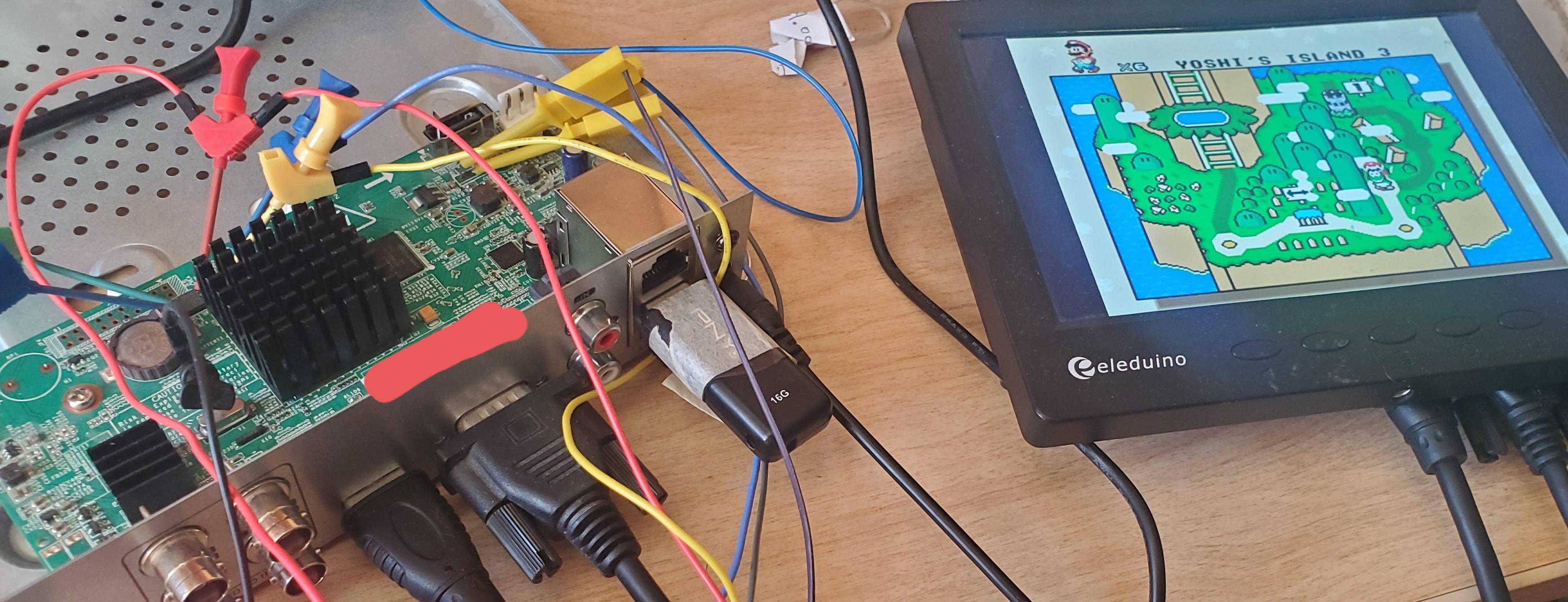
Here is the first ever rendering that was done to see if the display was working. Note that there was no pixel conversion or upscaling code completed yet.
![]()